LM3914 VU Meter Circuit: Light Up Your Audio Like a Pro! Circuit lm324 led vumeter circuits opamp datasheet amplifier schema mikrocontroller skema utuk schematics electronica
So, I was tinkering around in the garage the other day, thinking about my old stereo system. You know, the one I built back in college. It still works great, but I thought it could use a little visual upgrade. Specifically, I wanted to add a VU meter. There's just something so satisfying about watching those LEDs bounce along with the music. I started looking around online for some schematics and ideas, and I stumbled across a couple of interesting options. I thought I'd share them here, just in case anyone else is looking for a fun weekend project.
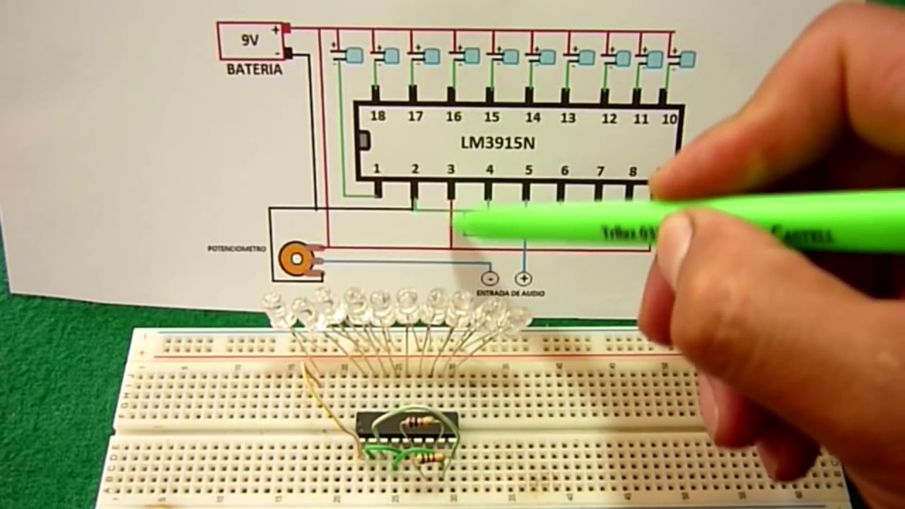
LM3915 VU Meter Circuit Diagram

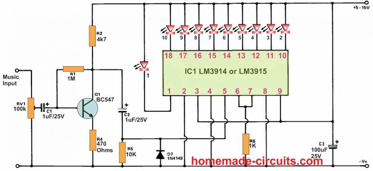
This circuit uses the LM3915, which is a pretty popular choice for VU meters. It's an easy-to-use IC that drives a series of LEDs to indicate the signal level. What's cool about the LM3915 is that it has a logarithmic scale, which is great for audio signals because our ears perceive sound logarithmically. This means that the steps between LEDs will seem more even in terms of loudness. The circuit diagram shows how to connect the LM3915 to an audio source, resistors for setting the current through the LEDs, and of course, the LEDs themselves. You can tailor the resistor values to adjust the brightness of the LEDs to your liking. Experimenting with different colored LEDs can also add a nice visual flair. I'm thinking maybe some cool blues and greens for a more modern look. You could even consider using a bargraph display instead of individual LEDs for a slightly different aesthetic. This particular diagram seems to show connections for pre-amplifier, amplifier and direct amplifier. This makes it flexible to implement into different configurations for your audio needs. One of the first things I'd do is breadboard it to test that the amplifier output and the VU Meter input is matched correctly. Remember to use shielded cables to prevent background noise.
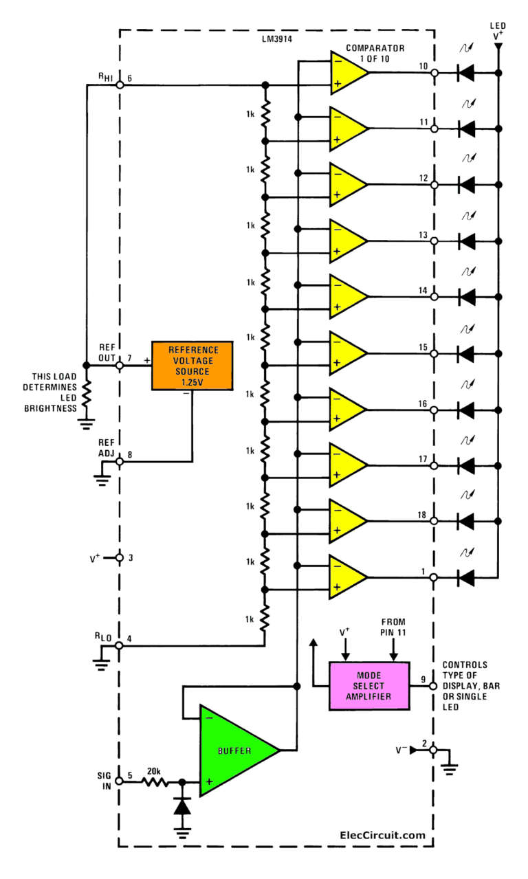
LM3914 VU Meter | Circuit Diagram

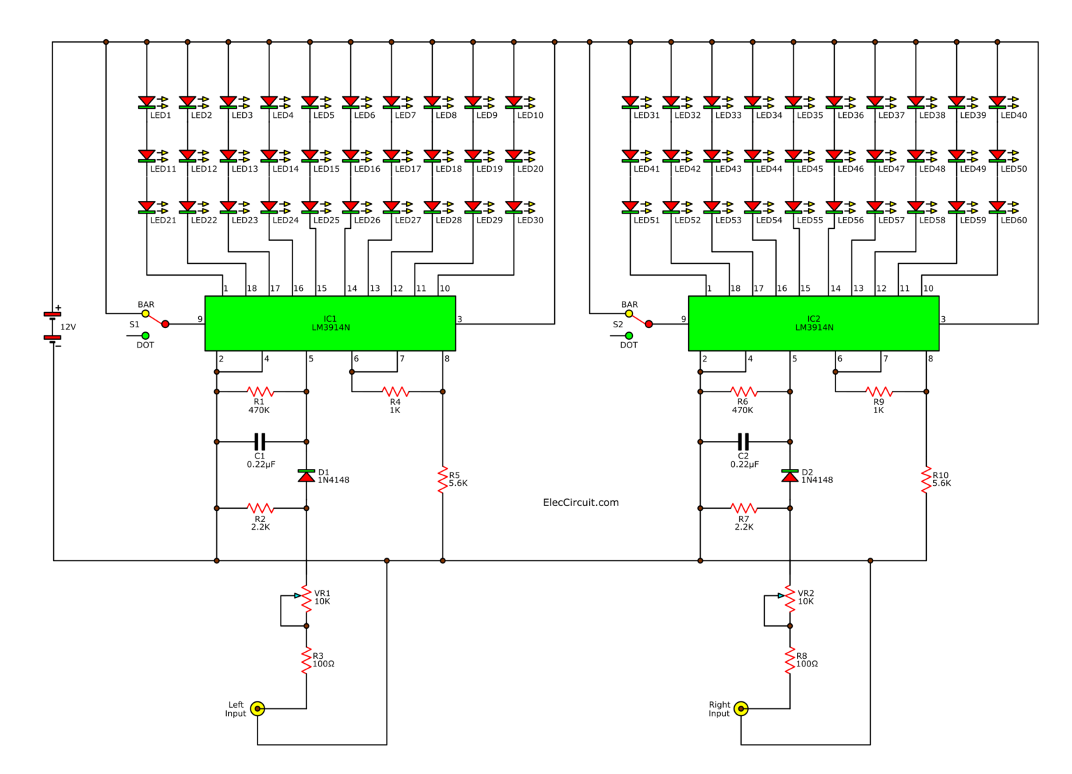
This one uses the LM3914, which is similar to the LM3915 but has a linear scale instead of a logarithmic one. This might be more suitable if you're working with a signal that isn't audio, or if you just prefer the visual representation of a linear scale. The basic principle is the same: the IC takes an input voltage and lights up a series of LEDs based on that voltage. One slight difference is that the LM3914 can be configured in either "dot" or "bar" mode. In dot mode, only one LED is lit at a time, representing the current signal level. In bar mode, all the LEDs up to the current signal level are lit, creating a bar graph effect. The diagram looks fairly straightforward, and I can see the configuration for the potentiometer to set the input sensitivity, which is crucial for calibrating the VU meter to your specific audio source. I think the "bar" mode would be the most visually appealing for a VU meter application. It also would be interesting to add a color changing LED as the signal increase to indicate the loudest peak. I would also use this circuit as a way to test the output signal from audio source to make sure the levels are safe for speakers or headphones.
So, there you have it – two different VU meter circuit options using the LM3915 and LM3914 ICs. Both are relatively simple to build, and they can add a cool visual element to your audio setup. Time to dust off the soldering iron!
If you are looking for Led vu meter circuit lm3914 – Artofit you've came to the right page. We have 25 Pictures about Led vu meter circuit lm3914 – Artofit like Audio VU Level Meter Circuit with LM324 |AUDIO AMPLIFIER SCHEMATIC, Electronic Circuit Diagrams: LM3914 VU Meter and also LM3914 VU Meter | Circuit Diagram. Here you go:
Led Vu Meter Circuit Lm3914 – Artofit
 www.artofit.org
 Points, Line Overflow LED Display Circuit With LM3914 - LED_and_Light
 www.seekic.com
 circuit lm3914 led display line overflow points light seekic overflowing when mode changes working point into has no ic
VU Meter Circuit Diagram One Transistor 6 LEDs - TRONICSpro
 pcb-design.pages.dev
 Electronic Circuits And Projects: How To Make An LED VU Meter Using LM3914
 circuitdigest.blogspot.com
 meter vu circuit led lm3914 electronic circuits projects using simple arduino circuitdigest make an how diy choose board
Lm3914 Vu Meter Circuit Diagram - Lm3914 220v Light Vu Meter Circuit
 smartcraft-wiring-diagram.blogspot.com
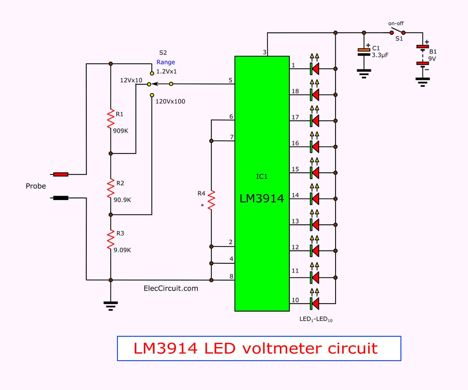
 voltmeter circuit lm3914 eleccircuit circuits ic vu light wiring ranges 50v probe
Audio VU Level Meter Circuit With LM324 |AUDIO AMPLIFIER SCHEMATIC
 audio-schematic.blogspot.com
 circuit lm324 led vumeter circuits opamp datasheet amplifier schema mikrocontroller skema utuk schematics electronica
LM3914 Datasheet Dot/Bar Display Driver | VU Meter Circuits
 www.eleccircuit.com
 lm3914 circuit voltmeter vu 2v circuits 1000v datasheet voltage eleccircuit scale full driver adjustable
LM3914 Datasheet Dot/Bar Display Driver | VU Meter Circuits
 www.eleccircuit.com
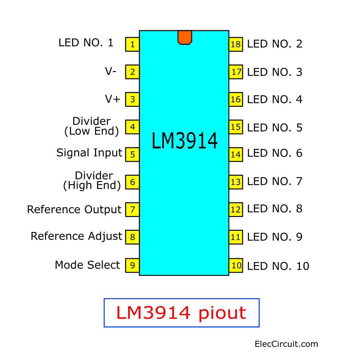
 lm3914 pinout circuits datasheet eleccircuit
What Is Vu Meter Circuit At Christy Finch Blog
 storage.googleapis.com
 How To Make Audio Level, VU Meter Using LM3914 Ic
 ruclips.net
 Lm3915 Vu Meter Circuit Diagram
 www.circuitdiagram.co
 Simple Led Vu Meter Circuit Diagram - Circuit Diagram
 www.circuitdiagram.co
 Lm3914 Vu Meter Circuit Diagram - Lm3914 220v Light Vu Meter Circuit
 smartcraft-wiring-diagram.blogspot.com
 lm3915 circuit vu vumetro lm3914 lm device electronics barra triboelectric descripción
4 Simple VU Meter Circuits Explained - Homemade Circuit Projects
 www.homemade-circuits.com
 vu circuits simple indicator explained driver
LM3914 Datasheet Dot/Bar Display Driver | VU Meter Circuits
 www.eleccircuit.com
 lm3914 circuits eleccircuit stereo
Electronic VU Meter By LM3914 And LM3915
 www.eleccircuit.com
 vu meter lm3914 lm3915 pcb stereo electronic led circuit hold layout peak eleccircuit components main figure component form using
Electronic Circuit Diagrams: LM3914 VU Meter
 circuitdiagramfree.blogspot.com
 vu meter lm3914 circuit diagram schematic audio pin led circuits de article electronic ic
Adâncitură Rahat Buruiană Simple Led Vu Meter Circuit Zener Diode
 cristor.dz
 Schematic Diagram Of Led Vu Meter
 www.circuitdiagram.co
 Analog VU Meter Circuit Using Transistors
 www.eleccircuit.com
 vu meter led circuit analog increase transistor note
VU Meter Using LM358 ICs | Circuit Diagram
 www.circuitdiagram.org
 meter lm358 using vu ics circuit circuitdiagram
Transistor Vu Meter Circuit
 schematicstretched.z14.web.core.windows.net
 LM3914 Datasheet Dot/Bar Display Driver | VU Meter Circuits
 www.eleccircuit.com
 lm3914 meter vu datasheet circuits eleccircuit block
LM3914 VU Meter | Circuit Diagram
 www.circuitdiagram.org
 lm3914 meter vu circuit battery led sound audio activated diagram indicator switches sequential circuitdiagram
Lm3914 Vu Meter Circuit Diagram - Lm3914 220v Light Vu Meter Circuit
 smartcraft-wiring-diagram.blogspot.com
 lm3914 vu ic
Points, line overflow led display circuit with lm3914. Vu circuits simple indicator explained driver. Meter vu circuit led lm3914 electronic circuits projects using simple arduino circuitdigest make an how diy choose board